Doepfer A-115 Audio Divider
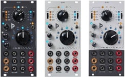
OverviewModule A-115 is a four-way frequency divider. The frequency of a signal at the input is halved (half frequency = first sub-octave), quartered (1/4 frequency = second sub-octave), and so on. In this way, the DIVIDER produces four sub-octaves (F/2 down to F/16).
At the output, the A-115 produces a summed mix of the original and the four sub-octaves. There are attenuators to control the amount (ie. Amplitude) of the original signal and each of the sub-octaves.
Bear in mind that the sub-octaves output by the A-115 are all true square waves. At the output there are always four square waves and the original signal available.
For more detailed information please look at the English user's manual ![]() A115_man.pdf
A115_man.pdf
Note: The new version of the A-115 (V2 2008) has an additional 3-terminal pin header with associated jumper available. JP3 at the top of the pcb (labelled "Source #1") is used to select if the original signal (i.e. the unchanged input signal of the In socket, not converted into rectangle) or the rectangle signal (derived from the input signal) is used for the Orig. control. In the left position of the jumper (towards the front panel) the unchanged original signal is used. In the right position the derived rectangle is used.
Width: 8TE / 8HP / 40.3 mm
Depth: 40 mm (measured from the rear side of the front panel)
Current: 20mA


