Verbos Electronics Scan & Pan
OverviewVerbos Electronics Scan & Pan
The Verbos Electronics systems need a small mixer module. One option would be to make it very simple with the focus on size. Mark Verbos decided it should do more.
The Pan & Scan (or Scan & Pan) is a 4 channel voltage controlled mixer with voltage controlled panning. Also, the scanning function from the Harmonic Oscillator is implemented to allow tricks that are not possible with any other mixer module. The signal path is all discrete transistors for the best sound quality.
SCAN & PAN
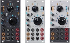
In a minuscule amount of space, the Scan & Pan provides a 4 channel mixer with voltage control of level and panning. Since the level control was already there, the "width" and "center" controls from the Harmonic Oscillator are included to allow the user to Scan across the channels, fade between them or actively mix them together. It's signal path is all discrete transistors.
• 14HP
• 50mA +12, 20mA -12
Scanning
The Scan & Pan’s main section on the lower left consists of 4 mixer channels. Audio inputs are at the bottom, the gain going into the channels is controlled by a gain control all the way at the top. The channel is at unity gain when the control is positioned at 9 O’clock. The signal path all the way through the module is built from discrete tansistors and some interesting distortion can be obtained by turning the gain higher. Also, low level signals can be boosted so signals levels are matched when scanning. The slider controls the level of the channel VCA, the jack below the slider is for CV control of the VCA. The “center” and “width” controls on the right allow selecting a channel or section of channels from external voltage or the panel controls, like the similar controls on a Harmonic Oscillator. Also, the CV inputs in the SCAN section have reversing attenuators to allow scaling and inverting control voltages coming in.
Panning
The position left to right or “panorama” of each channel’s signal is controlled by the “pan” control. External control voltage can also be used from the jack below the control. The position is indicated by the yellow or red LEDs lighting up. Their brightness is an indication of level and color is an indication of left (yellow) or right (red). Signal output for the left and right channels come from the jacks at the upper right.


