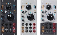
Doepfer A-141-2 Voltage Controlled Envelope Generator VCADSR / VCLFO
OverviewModule A-141-2 is the successor of the obsolete former VCADSR module A-141. Compared to the A-141 a lot of improvements and expansions have been added:
common control voltage input for all time parameters (A/D/R), range switch for three different time ranges, inverted ADSR output, additional output with voltage controlled level (i.e. built in output VCA), digital outputs for End of Attack (EOA) and End of Release (EOR), EOR is e.g. required for the VCLFO mode.
Features overview:
voltage controlled envelope generator (ADSR type = Attack - Decay - Sustain - Release)
manual controls and control voltage inputs with attenuators for all parameters (A), Decay (D), Sustain (S) und Release (R), increasing the control voltage at the inputs CVA, CVD or CVR increases the envelope time. The effects of the control voltages can be adjusted by means of the assigned attenuator controls CVA, CVD and CVR. Same applies for Sustain. But Sustain is a voltage level rather than a time parameter.
common control voltage input (Comm.CV) for the three time parameters A, D and R. This input can be used e.g. to shorten all times for higher notes (like piano and many string instruments). In VCLFO mode this input can be used to control the frequency. By means of a jumper it can be chosen if an increasing control voltages increases the times A, D and R (same polarity as the CV inputs CVA, CVD and CVR) or if it lowers the times (and consequently increases the frequency in VCLFO mode, same polarity as the CV of a VCO). To adjust the sensitivity of this input an external attenuator (e.g. A-183-1) or attenuator/polarizer/offset generator (e.g. A-183-2) can be used.
three-position time range switch 10:1:100 with the approximate time ranges 50us ... 6 s (position "x1"), 500us ... 60s (position "x10"), 5ms ... 10 min (position "x100")
Gate input: a low/high transition starts the envelope (Attack phase followed by the Decay/Sustain phase), a high/low transisiton finishes the envelope (Release phase), the voltage level of the high state of the gate signal may range from +5V to +12V
Retrigger input: while the gate is high, a trigger pulse received at the retrigger socket will re-start the envelope from the beginning of its attack phase, the voltage level of the retrigger signal may range from +5V to +12V
normal envelope output (Fixed Out) with fixed level (about 0...+7V)
invertierted envelope output (Inv. Out) with fixed inverted level (about 0...-7V)
variable envelope output (Var.Out) control voltage input (Lev.CV) that controls the level of this output (nothing but an additional VCA behind the fixed output), e.g. for dynamic applications, where the envelope level is controlled by a velocity voltage, +5V control voltage corresponds to amplification +1 (i.e. the same +7V level as the fixed output), control voltages beyond +5V are possible and will increase the level until clipping occurs at about +12V. The Lev.CV input is normalled to +5V, i.e. if no cable is patched into Lev.CV the Var.Out can be used as a second ADSR with fixed level
two different modes of the variable envelope output can be selected by means of an internal jumper: normal VCA mode (as described above) or Polarizer mode (in this mode 0V CV corresponds to inverted envelope signal, about +2.5V correspond to no signal and +5V correspond to non-inverted envelope).
End-of-Attack output (EOA): this output turns high as soon as the Attack phase is finished and the Decay/Sustain phase begins
End-of-Release output (EOR): this output turns high as the fixed envelope signals falls below about +0.1 V (the threshold can be adjusted by means of a trimming potentiometer, the factory setting is +0.1V). The EOR signal turns low as soon as the Attack phase ends. This signal can be used to built a VCLFO with adjustable rising and falling time. For this EOR has to be patched to the Gate input. Then the module works as kind of a VCLFO. The common control voltage input can be used in addition to control the frequency by means of an external voltage (inverted scale as mentioned above), the shapes of the attack and release phase can be modified as described in the following paragraph
The control voltage inputs for A, D and R can be used also to change the shape of each segment. To change the shape of the Attack curve the inverted envelope output (Inv. Out) has to be patched to the CVA input. Then the CVA control is used to modify the shape of the Attack segment (CCW = usual exponential shape, about center position = linear shape, CW = inverse exponential shape). Same is valid for the shapes of Decay and Release also. But for this the non-inverted output (Fixed Out) has to be patched to the CV input in question (CVD or CVR or both).
The time control input sockets can be normalled by two internal jumpers (i.e. CVA socket -> CVD socket and CVD socket -> CVR socket). With this it's possible to control e.g. Decay and Relase with the same voltage without the need of an external multiple.
display of the envelope signal by means of an LED
The gate signal can be picked up from the internal gate signal of the A-100 bus by means of a jumper.
This document explains the functions of the jumpers: A141_2_Jumper.pdf
Width: 14 TE / 14 HP / 70.8 mm
Depth: 70 mm
Current: 40 mA


