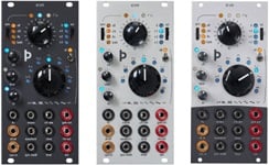
Doepfer A-143-1 Complex Envelope Generator / Quad AD-Generator / Quad LFO
OverviewOverview: Module A-143-1 is a complex envelope generator that consists of Attack/Decay generators. For the complex envelope generator the four units are daisy-chained, i.e. the preceeding unit triggers the following unit. The four units can be used even as four separate AD generators (switch position AD) or AD-type LFOs (switch position ).
Details: Module A-143-1 contains four separate attack/decay type envelope generators. Each unit can be switched into a free running mode (LFO mode). The LFO mode differs in several points from a regular LFO (like A-145, A-146 or A-147): The slopes are exponential - in contrast to linear slopes of a normal LFO, and the frequency is defined by both controls. The attack control defines the time of the rising slope, the decay control the falling slope.
Each unit has available a comparator that compares the AD output voltage with a manually adjustable threshold and switches the corresponding comparator output (Cp 1...4) to "high" as soon as the AD output voltage goes in the decay phase below this value. The comparator output is normalled to the trigger input of the next stage via the switching contact of the trigger input socket. Consequently the first unit triggers the second, the second triggers the third and so on.
Each AD generator is equipped with a Polarizer (look at the Voltage Controlled Polarizer A-133 concerning details about the polarizer function) and a mixer that adds up all polarizer outputs. This allows to add up all AD/LFO output signals inverting or non-inverting with adjustable level to the mix output. Additionally a single output (Env 1...4) is available for each unit.
If the trigger input of unit 1 is controlled by a normal gate signal (e.g. from a keyboard resp. MIDI-to-CV/Gate interface) one obtains a very complex envelope signal at the mix output. The signal contains 8 segments controlled by Attack 1, Decay 1, Attack 2, Decay 2, Attack 3, Decay 3, Attack 4 and Decay 4. The transition between the stages (i.e. when the following AD generator is triggered) is controlled by threshold knob. The positive or negative contribution of each unit to the mix signal is adjusted with the Mixing Polarizer control. If the trigger input of unit 1 is controlled by the comparator output of unit 4 one obtains a 8 stage LFO.
The single AD outputs can be used to control VCAs or VCFs that open one after another corresponding to the AD signals (a little bit similar to the Shepard generator A-191).
The default-connection between the four units (CPn = Trig.n+1) can be interrupted by patching cables into the trigger inputs. Consequently the four units can be used as separate AD generators or LFOs. In any case the mix signal is available (e.g. mix of four AD generators or LFOs with adjustable level and sign).
In the LFO mode the comparator output serves as LFO rectangle output with adjustable pulse width (= threshold control).
Each unit is equipped with a separate LED display for envelop and comparator output. The shortest attack/decay time is about 5 ms, the longest attack/decay times are about 3 seconds (attack) / 10 seconds (decay). By changing the value of a capacitor the shortest time can be modified (details can be found here: A100_Capacitors.htm).
The sketch at the bottom of the page shows the module principle with 4 daisy-chained AD units (as predetermined by the normalled sockets), that are mixed with the integrated polarizing mixer.
A detailed description of the module can be found in the user's manual ![]() A1431_man.pdf.
A1431_man.pdf.
The second picture shows the principle of the module with four daisy-chained AD units (as predetermined by the normalled sockets), that are mixed with the integrated polarizing mixer. Each unit is triggered by the comparator output of the preceeding unit. The settings for A, D and comparator threshold are different for each unit. The four envelopes are added up in the polarizing mixer. The mixer outputs for two different settings of the mix controls are shown: V = 1 for all units; V = 1 for the units 1 and 4 and V = -1 for the units 2 and 3. Of course the four envelopes can be added up in any desired amplitude and polarity.
The dashed curve shows the mix output in the LFO mode (i.e. Cp4 out connected to Trig In 1).
Width: 28 TE / 28 HP / 141.9 mm
Depth: 50 mm
Current: 70 mA


