Thorn.audio - VC LFO (Silver)
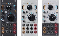
OverviewThorn.audio - VC LFO (Silver panel)
Fully voltage controllable Eurorack format, externally syncable, 16 waveform low frequency oscillator with built-in VCA and sample & hold.
Powered by a socketed VCLFO10 IC from Electric Druid.
Suitable for precision modulation, live performance as well as educational purposes.
- Height: 3U (128.5mm)
- Width: 12hp (60.6mm)
- Depth from panel: 31mm
- Depth total: 51mm
- +12v: 80mA
- -12v: 60mA
- Fully voltage controllable
- Externally syncable in three different modes
- Four frequency ranges by octaves, from 0.05Hz to 102.4Hz
- 16 distinct waveforms in two sets of eight
- Waveform distortion
- Sample and Hold
- VCA
- Gate output
- Inverted output
- Visual feedback on all incoming CV
- Easily reprogrammable
Controls:
1. Incoming sync indicator
Lights up while sync input(20) is high. Sync effect depends on sync mode switch setting(4).
2. LFO output indicator
Blue when output(23) voltage is below -2v, red when above +2v. Doubles as frequency/waveform indicator. Affected by level(9) setting so it will be unresponsive below a certain output level. In this case one can refer to the Gate output LED(3) for indication on the state of the current cycle.
3. Gate output indicator
Lights up white while output(23) voltage is positive and gate output(15) is +5v.
4. Sync mode switch
- Off: sync input(20) is ignored.
- S/H: sync sample and hold rate(7) to incoming sync pulses(20).
- LFO: reset selected waveform(10) on incoming sync pulses(20).
- Both: resets waveform(10) and triggers sample and hold(7) on sync pulse(20).
5. Frequency knob
adjust frequency(2) within selected range(6). Left is slower, right is faster.
6. Octave range selection switch
- 0: 0.05Hz to 12.8Hz
- +1: 0.1Hz to 25.6Hz
- +2: 0.2Hz to 51.2Hz
- +3: 0.4Hz to 102.4Hz
7. Sample and hold rate knob
Controls how often the current state of the waveform(10) is sampled. All the way turned to the left(CCW) is off, then rate increases by clockwise rotation. Turning it on affects all the outputs(15, 19, 23). This rate can be controlled by the sync input(20) when the sync mode switch(4) is in the S/H or BOTH setting. To simply control it from an external clock connected to the sync input(20), set it to a slower rate than the incoming trigger rate.
8. Skew amount knob
allows you to shift the center point of the selected waveform(10) left or right from 12.5% up to 87.5% of the cycle duration. The noise waveform is not affected by this setting, but the random waveform(the alternative mode(11) of the noise waveform) is.
9. Level knob
sets output(19, 23) level from 0v to +-5v, affected by the level cv input(22). Note that output LED(2) goes dark below a certain output level.
10. Waveform selection switch
controls which waveform is output(15, 19, 23) by the module, affected by the alt toggle switch(11), note the small legend illustrating the alternative set below the knob.
11. Alternative waveform switch
toggles between the original set of waveforms(10) and their alternative counterparts. The alternative set consists of a mixture of pulsed modes and more complex variants of the original set. Refer to the legend printed below the large knob(10) for an idea of the alternative waveforms.
Inputs and outputs:
12. Frequency input
Receives -5v to +5v CV which is summed with frequency knob(5) setting.
13. Octave CV input
Receives -5v to +5v CV which is summed with octave switch(6) setting. This changes the range of the frequency knob(5).
14. Sample and hold rate input
Receives -5v to +5v CV which is summed with S/H knob(7) setting.
15. Gate output
Outputs a 0v to +5v square wave which goes high when LFO output is above 0v. Useful for clipping LFO output using a VCA for instance. Indicated by the gate output LED(3).
16. Alternative waveform input
Receives a 0v to +5v square wave input to toggle between the two waveform(10) sets, bypasses the alt toggle switch(11).
17. Waveform selection input
Receives -5v to +5v CV which is summed with waveform selection rotary switch(10) setting.
18. Waveform distortion input
Receives -5v to +5v CV which is summed with skew knob(8) setting.
19. Inverted output
Outputs -5v to +5v CV inverted with respect to normal output(2, 23). Meaning this output is the mirror image of the normal output.
20. Sync input
Receives a 0v to +5v square wave input which triggers a reset on the rising edge. Type of reset depends on the settings of the sync mode switch(4). The sync indicator LED(1) lights up when this input senses a higher voltage.
21. Sync mode input
Receives -5v to +5v CV which is summed with sync mode switch setting(4).
22. Level input
Receives -5v to +5v CV which is summed with lvl knob(9) setting. This controls the amplitude of the outputs(19, 23).
23. Output
LFO -5v to +5v CV output, indicated by the output LED(2). Amplitude adjustable by the level knob(9) or by the level CV input(22).
Additional notes
The core idea behind this module is all about control voltage. Hence all features are individually broken out to CV inputs, making the most use possible of the benefits of the digital wavetable oscillator. This means that the design is geared towards allowing hands-off control of all aspects and some concessions have been made to that effect.
Initial setup basically consists of connecting the power cable to the module and your bus. The cable has a slotted socket for correct orientation, but mind that the red stripe faces the white line on the edge of the pcb. The included screws are nylon in order to minimise rack-rash.
Tuning the module is possible by adjusting the small smd trim potentiometer on the back. It adjusts the offset voltage that affects the center point of the lfo oscillations. It should be close to its three o'clock position, but you can adjust it by turning the module on, reducing the output level to almost zero and turning the trim potentiometer until you find the point where the gate output led just barely turns off.
The LFO sync type is hard sync, meaning that it resets the current cycle to the beginning of the waveform. It does not control the duration of the cycles. This allows you to further shape the output to, say, three quarters of a sinewave by using external sync and adjusting the HZ knob so the duration of a cycle is just a little longer than the time between incoming sync pulses.
Color coded nuts indicate the type of jack, with gold representing Gate/Trigger input, black is +-5v CV inputs and red jacks are outputs.
The CV inputs are scaled down to +-2.5v and added/subtracted with the knob setting, meaning that to sweep the full range of the parameter with CV, the knob should be in center position. The inputs are clipped to the allowed range after mixing, so you can apply any eurorack voltage here.
The module's core processor is socketed, so using a simple PIC programmer and some basic Assembly knowledge you can modify its functionality to suit your needs.
The code is written by Electric Druid who supplies me the chips preprogrammed.
Assembly code
HEX code
VCLFO10 datasheet
PIC16F1825 datasheet
Compatible programmer
more info: https://thorn.audio/VCLFO


